Choosing a phased array ultrasonic flaw detector starts with the inspection you need to deliver. A clear image on a demonstration block is useful, but buyers also need to know whether the complete system fits their weld geometry, access restrictions, reporting workflow and inspection procedure.
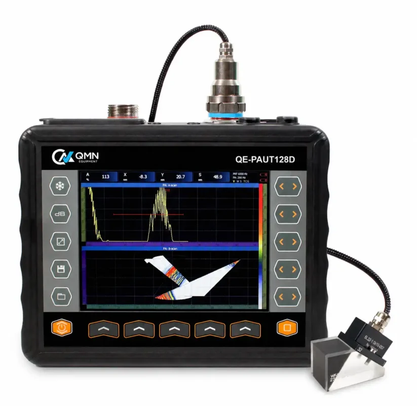
This guide explains how to compare PAUT equipment as a working package: instrument, probes, wedges, scanner, calibration blocks and software. QMN’s QE-PAUT128D phased array ultrasonic flaw detector provides a practical product reference. Its listed capabilities include phased array testing, time-of-flight diffraction and conventional ultrasonic testing; the final configuration should be checked against your application before ordering.
Start with the inspection brief
Prepare a short brief before comparing model numbers. Identify the material, thickness range, weld preparation, component diameter, expected discontinuities and accessible scanning surfaces. Include drawings or photographs showing nearby fittings, supports and other obstructions. State whether access is available on both sides of the weld.
Then define the deliverable. Does the customer require stored inspection data, position-referenced scans, offline analysis or a particular report format? Identify the governing code, contract requirements and approved procedure. These details turn a general equipment enquiry into a configuration that suppliers can review meaningfully.
Separate your immediate work from possible future applications. A system selected for repeatable carbon-steel weld inspection may need different probes, techniques and validation for castings, austenitic welds or complex geometry. Ask suppliers to identify which applications they have actually assessed for your proposed package.
PAUT selection roadmap
1. Define the job
Material, geometry, target coverage and access.
2. Match the package
Instrument, probes, wedges and scanner.
3. Demonstrate it
Representative part, calibration and saved data.
4. Confirm delivery
Accessories, documentation, training and acceptance.
A purchasing workflow, not a test result or a substitute for an inspection procedure.
Understand what phased array adds
PAUT uses a probe containing multiple elements. Controlled timing delays allow groups of elements to steer and focus the sound beam. ASTM E2700 describes this principle for contact ultrasonic examination of welds using phased arrays. It does not mean that buying a particular instrument automatically establishes an acceptable inspection.
A sectorial scan, or S-scan, brings together responses from a range of beam angles. The associated A-scan remains important for evaluating individual signals. Encoded displays can also relate ultrasonic responses to scanning position. Choose displays that support the required interpretation and records, rather than judging equipment by screen appearance alone.
Conventional UT may still be appropriate for some tasks. PAUT becomes particularly useful when an inspection benefits from multiple beam angles, electronic scanning or recorded imaging. The decision should follow the inspection objective and the demonstrated performance of the complete setup.
Read channel specifications carefully
Channel notation, probe element count and physical probe connectors describe different things. A probe with many elements does not imply that all elements are excited together. The active aperture is the group used to form a beam, while the instrument architecture determines how those groups can be selected and driven.
Manufacturer terminology should be confirmed explicitly. Ask how many elements can be used in one active aperture, which probe configurations are supported, and whether the intended inspection groups can run together. Evident’s technical guidance also notes that a higher focal-law count does not necessarily provide more useful functionality.
The QMN product page lists two 64-channel phased-array probe connections. Treat that as a starting point for discussion: request confirmation of the generator configuration, supported probes and acquisition arrangement in the quotation. Two connectors alone do not establish every possible simultaneous inspection mode.
Select probes and wedges for the material
Probe frequency, element arrangement and aperture affect beam behaviour. Higher frequency can support sharper focusing, but attenuation generally increases with frequency, reducing penetration. Long sound paths and highly attenuating materials can therefore require lower frequencies. There is no single frequency that is best for every weld or component.
Wedge selection must also match the intended inspection. Check the probe interface, acoustic design, footprint, scanning surface and available clearance. On curved components, confirm the proposed contact arrangement. A package that works on flat plate may need a different wedge configuration for a small-diameter pipe.
Provide the supplier with the most difficult representative part, not only the easiest one. Ask for a demonstration using the intended probe and wedge combination. For challenging alloys or dissimilar weld materials, specialist techniques may be needed; a general claim of PAUT capability is insufficient evidence of coverage.
Decide whether you need encoded scanning
An encoder links probe travel to position in the recorded data. This is valuable when you need a traceable indication location or a scan record that another qualified reviewer can revisit. Manual unencoded scanning can provide useful information, but it does not automatically provide the same position reference.
Evaluate the scanner as part of the inspection package. Check mounting clearance, probe spacing, couplant delivery, cable routing and travel around the component. Ask the demonstrator to show how position is established and verified, and how incomplete or interrupted scans are identified.
Compare acquisition performance with your actual settings. Focal laws, inspection groups, recording options and scan resolution can affect practical performance. A display refresh specification should not be treated as a guaranteed inspection speed. Request a recorded demonstration with the configuration you intend to use.
What each part of the package contributes
Component
Main contribution
Buyer’s check
Probe and wedge
Introduce the planned sound beams
Material, geometry and contact fit
Scanner and encoder
Guide travel and reference position
Access and position verification
Reference blocks
Support calibration and checks
Suitability for the procedure
Analysis software
Review, measure and report data
Reopening files and report workflow
Qualitative equipment map; no measured performance or comparative rankings are implied.
Evaluate TOFD as a separate technique
Time-of-flight diffraction uses transmitted ultrasound and a receiving probe to collect diffracted signals, including responses from discontinuity tips. It offers another way to obtain information about weld discontinuities and their dimensions. It needs its own probe arrangement, setup and interpretation.
If TOFD is part of your procedure, ask the supplier to identify the required probes, wedges, spacing and scanner hardware. Confirm how coverage and technique limitations will be addressed on the actual thickness range. The availability of a TOFD mode is only one part of a usable TOFD inspection package.
Make calibration and data review part of the demonstration
Phased-array calibration involves more than making one reflector appear on screen. Wedge-delay compensation and sensitivity normalization address differences across the focal laws used in the inspection. Depending on the procedure, distance-amplitude correction or time-corrected gain may also form part of the setup.
Ask the demonstrator to show the applicable calibration sequence, save the setup and reopen it. Then review the recorded inspection data on the software that your team will use. ASNT’s introductory guidance highlights software, data storage and data manipulation as important parts of practical phased-array work.
Request a sample report and establish who can access analysis software, whether licences are included, and which export functions are available. Include these items in the purchase scope. A screenshot is useful for discussion, but it is not equivalent to having the underlying inspection data available for review.
Build a complete quotation and acceptance plan
For the QE-PAUT128D PAUT, TOFD and conventional UT platform, QMN states that application-specific probes, wedges, scanners, encoders and calibration blocks are included only when identified in the final quotation. Confirm every required item individually, including cables, adapters, batteries and charging arrangements.
Agree on acceptance evidence before ordering: a representative demonstration, the supplied configuration, documentation, software access and any agreed training. Distinguish equipment verification from personnel qualification and procedure approval. None should be assumed merely because a product page references a standard.
When requesting a PAUT equipment quotation, send your inspection brief and ask for a clearly itemized package. That makes competing offers easier to compare and gives both parties a practical basis for confirming that the delivered system matches the intended work.
Frequently asked questions
1. What should I specify when buying a phased array ultrasonic flaw detector?
Specify the material, thickness, weld geometry, access, inspection procedure and reporting needs. Ask for the complete probe, wedge, scanner, calibration and software configuration, with a demonstration relevant to your application.
2. Does a higher channel count always mean a better PAUT system?
No. Channel capability must match the required probe aperture and inspection arrangement. Software, calibration, acquisition and physical access also matter. Compare demonstrated performance on representative parts, rather than selecting by one specification.
3. Are probes and scanners included with the QE-PAUT128D?
The product listing identifies these as application-specific items included only when stated in the final quotation. Confirm probe models, wedges, scanner, encoder and calibration blocks before ordering.
4. Do I need an encoder for every phased-array inspection?
That depends on the approved procedure and required records. An encoder provides position-referenced acquisition. Unencoded manual scanning can be useful, but confirm whether it satisfies the project’s coverage and documentation requirements.
5. Can one instrument support PAUT, TOFD and conventional UT?
Some platforms, including the listed QE-PAUT128D, support all three. Each technique still needs an appropriate setup and accessories. Confirm that your required acquisition arrangement is supported in the configuration being quoted.
A practical guide to selecting and using a ferrite meter for stainless-steel welds, covering Ferrite Number, probes, calibration, surface effects and inspection records.
A practical guide to selecting metallographic cutting, mounting, grinding and polishing equipment, including consumables, utilities, workflow and preparation-quality checks.
Compare Leeb and UCI portable hardness testing by component rigidity, surface condition, material calibration and reporting requirements, with a practical equipment-selection checklist.
Choose a Charpy impact tester around your test methods, energy range and laboratory workflow. Review specimen preparation, installation, verification and the complete purchasing package.