Ferrite Meter Selection Guide for Stainless Steel Weld Inspection
A ferrite meter for stainless steel welds is useful only when the instrument, probe, calibration and inspection procedure match the question being asked. The same displayed value can be misleading if one party expects Ferrite Number (FN), another expects a metallographic phase percentage, or the probe is used on a curved, thin or rough surface without evaluating the effect.
This guide explains how to select a handheld ferrite meter and build a defensible measurement workflow. It applies to austenitic and duplex ferritic-austenitic stainless-steel weld metal, cladding and accessible components. It does not assign universal acceptance limits: the applicable construction code, material specification, welding procedure or project requirement must define the required range and reporting basis.
Start with the required result: FN or phase percentage
Ferrite Number is a standardized magnetic-response scale used for weld metal. It is not automatically the same as the volume percentage of ferrite seen in a polished and etched microstructure. AWS A4.2M:2020, which modifies ISO 8249:2018, describes calibration procedures intended to make magnetic-instrument measurements reproducible and reportable as FN. The standard also distinguishes the scope of calibrated weld-metal measurements from broader claims about absolute phase fraction.
If a specification asks for FN, select an instrument and calibration route that support the named standard and the necessary range. If the engineering question concerns the spatial distribution, morphology or volume fraction of phases, metallographic image analysis or another specified laboratory method may be required. Do not create a conversion between FN and percentage unless the governing document or a validated procedure explicitly permits it.
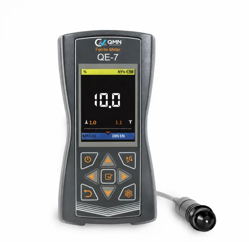
Older specifications may cite withdrawn or superseded documents. For example, ISO 17655:2003 is withdrawn. Procurement documents should identify the exact applicable edition rather than relying on a product page’s general standards list. QMN’s QE-7 ferrite meter displays both percentage and FN scales, but the user remains responsible for choosing the scale required by the inspection plan.
Choose the measurement route by the required output
Ferrite Number required
Use a magnetic instrument calibrated and verified for the specified FN procedure and range.
Phase percentage required
Use the specified quantitative method; do not substitute FN without documented authorization.
Process trend required
Define fixed locations, repeated readings and control criteria before collecting production data.
This decision map is methodological guidance, not an acceptance table or a test result.
Understand what a magnetic-induction instrument detects
In magnetic-induction measurement, an energized probe creates a magnetic field. Magnetic phases in the test area change that field, and the instrument converts the response through its calibration. This allows quick, nondestructive readings on accessible surfaces without cutting a section from the component.
The method has an important limitation: it responds to magnetic phases, not exclusively to delta ferrite. Instrument-manufacturer guidance notes that magnetic induction cannot distinguish delta ferrite from deformation-induced martensite. Cold-worked austenitic stainless steel can therefore require special interpretation. The method also samples a finite volume near the probe; it does not show how ferrite is distributed through a weld or across individual beads.
A ferrite meter is therefore a measurement tool, not an automatic metallurgical verdict. The procedure must state the material condition, measurement location, reporting unit and applicable acceptance source. If the objective is to resolve phase morphology or investigate an unexpected magnetic reading, use metallography or another specified technique to answer that different question.
Six criteria for selecting a ferrite meter
1. Applicable standard and calibration. Confirm that the instrument can be calibrated or verified for the method named by the customer. AWS A4.2M:2020 describes primary and secondary standards for magnetic instruments. Ask what reference standards are supplied, their stated values and traceability, and what routine verification the manufacturer requires.
2. Measurement range and scale. The required FN or percentage range must fall within the instrument and probe configuration. The QE-7 product page lists configurable percentage ranges and an FN range extending from 0.5 to 100, with an asterisk indicating configuration-dependent specifications. Confirm the ordered range and supplied probe in the final quotation rather than assuming every configuration includes the maximum range.
3. Probe geometry and measurement locality. A broad probe may average a larger zone, while a smaller probe may better access narrow weld beads, cladding boundaries or restricted areas. QMN lists a QE2-01 transducer in the delivery set and a QE0.7-01 localized transducer as optional. Review tip dimensions, access, edge clearance, curvature and the effective sensing volume on representative components.
4. Surface and component geometry. Curvature changes the probe’s magnetic circuit. Thin sections, edges, small parts and nearby magnetic material can also influence readings. A demonstration on the actual diameter, thickness and surface condition is more valuable than a check on a convenient flat block alone.
5. Data handling. For production work, look beyond a single displayed reading. Useful functions include minimum, maximum and mean values, storage, specimen or weld identifiers and export. The QE-7 page lists discrete and continuous modes, non-volatile memory, statistics and USB connectivity. Decide whether these functions fit the organization’s reporting and data-integrity practices.
6. Field suitability. Confirm the operating-temperature limits, enclosure protection, battery arrangement, display readability, carrying protection and replacement-probe availability. Treat environmental ratings as equipment limits, not permission to ignore the site’s safe-work controls.
Control the largest sources of measurement variation
Probe position is critical. The sensing pole should contact the test surface as intended by the manufacturer, without rocking or excessive pressure. Tilting changes the coupling and can increase scatter. On a narrow weld crown, the probe footprint may extend into adjacent base material, so the chosen probe must fit the defined measurement zone.
Curved surfaces can cause systematic error if the instrument was adjusted on a flat reference. Manufacturer guidance indicates concave and convex surfaces can shift readings in opposite directions. Very thin material can also allow part of the magnetic field to extend beyond the specimen. Helmut Fischer notes that thickness effects can become relevant below 2 mm for its described measurement system; users should apply the limits and correction approach specified for their own instrument and probe.
Roughness can produce different readings depending on whether the probe sits on a peak or in a valley. Clean the location as the approved procedure allows, take enough readings to characterize the defined area, and investigate outliers rather than deleting them without a rule. Surface preparation must not alter the material condition that is being evaluated.
Ferrite-measurement record checklist
Record
Why it matters
Instrument, probe and serial number
Identifies the complete measurement system.
Reference standard and verification result
Shows the system was checked for the required range.
Material, weld and surface condition
Provides context for magnetic and geometry effects.
Location map and individual readings
Makes averages and repeat measurements traceable.
Required unit, acceptance source and disposition
Prevents FN, percentage and engineering limits from being mixed.
The governing procedure determines the actual fields and sampling frequency.
Build a repeatable field workflow
First, review the drawing, weld procedure, material specification and inspection instruction. Mark the required zones and confirm whether readings are to be reported individually, as an average or by another rule. Verify that the instrument, probe and reference standards cover the expected range.
Second, allow the equipment and reference materials to stabilize under the conditions required by the manufacturer. Inspect the probe pole and cable, then perform the prescribed zero, adjustment or verification sequence. A check that fails should stop measurement until the cause is resolved.
Third, identify each weld and measurement location before testing. Place the probe consistently, collect the specified number of readings, and retain individual values. If continuous scanning is used, define the path and speed in the procedure. Recheck the instrument at the required interval and after any event that could affect performance.
Finally, report the scale explicitly as FN or percentage, together with the instrument, probe, calibration or verification information, locations and surface condition. The QE-7 operation manual should be reviewed alongside the project procedure before field use.
Know when another NDT method is needed
Ferrite measurement does not locate cracks, size discontinuities or measure remaining wall thickness. It characterizes magnetic response in austenitic and duplex stainless materials. A weld may meet its ferrite requirement and still require visual, liquid penetrant, radiographic, ultrasonic or other examination under the governing plan.
When the task is crack sizing rather than ferrite measurement, a dedicated crack-depth meter addresses a different inspection question. For encoded weld examination and volumetric data, the phased-array ultrasonic equipment guide explains other selection factors. QMN’s broader NDT equipment category can help buyers compare instrument families without treating them as interchangeable.
Prepare a useful request for quotation
A complete request should describe the stainless-steel grades, weld or cladding geometry, thickness, expected range, required output scale, governing document and edition, operating environment, data-export needs and reporting workflow. Include photographs or drawings showing access and curvature when possible. Ask the supplier to identify the exact instrument range, supplied probe, optional probes, reference standards, documentation and verification recommendations.
Before purchasing, arrange a practical evaluation on representative parts. Confirm that the probe reaches the defined locations, produces stable readings, supports the required records and can be verified with the proposed standards. For configuration questions, contact QMN Equipment with the application details rather than selecting from range alone.
Frequently asked questions
1. Is Ferrite Number the same as percent ferrite?
No. FN is a standardized magnetic-response scale used for weld-metal measurement. It should not be treated as an exact volume percentage unless a governing document or validated procedure supplies an appropriate relationship.
2. Can a ferrite meter be used on duplex stainless steel?
Yes, suitable magnetic instruments can measure duplex ferritic-austenitic stainless steel, but the instrument range, probe, calibration and acceptance criteria must match the application. Confirm the specific grade, geometry and required reporting scale before testing.
3. How often should a ferrite meter be verified?
Follow the governing procedure, applicable standard and manufacturer’s instructions. Verification is normally tied to the measurement session and should also be repeated after events that could affect the instrument, probe or reference setup.
4. Why do ferrite readings change on a curved weld?
Curvature changes the magnetic path between the probe and the component. A setup adjusted on a flat reference can therefore show systematic differences on concave or convex surfaces unless the instrument’s approved correction or calibration approach is used.
5. Can a ferrite meter detect weld cracks?
No. A ferrite meter measures magnetic response associated with ferrite and other magnetic phases. Crack detection requires the NDT method specified for the component, such as penetrant, magnetic particle, eddy-current or ultrasonic examination where applicable.
A practical guide to selecting and using a ferrite meter for stainless-steel welds, covering Ferrite Number, probes, calibration, surface effects and inspection records.
A practical guide to selecting metallographic cutting, mounting, grinding and polishing equipment, including consumables, utilities, workflow and preparation-quality checks.
Compare Leeb and UCI portable hardness testing by component rigidity, surface condition, material calibration and reporting requirements, with a practical equipment-selection checklist.
Choose a Charpy impact tester around your test methods, energy range and laboratory workflow. Review specimen preparation, installation, verification and the complete purchasing package.